
Powering through – Voima passed the EFBE TRI-TEST® Cat-5
The Voima has a lot more going on other than the world’s first 190mm, CNC machined, and bonded E-bike.
Considerable structural considerations have been made during the design process. When combined with our new manufacturing process, the result is an E-bike frame that can withstand the most demanding riding day after day.
As a testament to this, we’re so happy to say that the Voima E-bike has passed the rigorous EFBE test protocol. Here we talk in more detail to learn more about what goes into it and get a perspective of the phases the frame needs to pass.
A Reference Point
First of all, why test?
Objective testing is the basis of the scientific method. Everything outside of that is more or less educated guesswork. Testing done scientifically in a controlled lab setting can validate the tested design, or point out possible shortcomings. This then helps define any potential need for further developmental work.
Can real-life riding conditions (over multiple years of intensive use) be replicated in a tightly controlled lab setting in just a few days?
Perhaps not. The forces and stresses that a frame and components are subjected to on the highest levels of riding are very, very hard to quantify. And according to the current understanding, no verified data exists on this front. What we can do though is to test the frame – or other components – according to the strictest testing protocol there is. And that’s exactly what we did.
The Voima E-bike frame was sent to EFBE Prüftechnik GmbH in Germany to go through the EFBE TRI-TEST® GRAVITY Cat-5 (the TRI-TEST also comes in other standards) which is a test designed specifically for gravity bikes. The test consists of the following;
- Pedaling Forces Fatigue Test
- Vertical Force Fatigue Test
- Head Tube Fatigue Test
- Brake Load Fatigue Test
- Rear Axle Load Fatigue Test
- Lateral Load Fatigue Test
- Maximum Load Test Pedal Load
- Maximum / Overload Test Jump/ Drop Load
When going through the list it becomes obvious quickly that the full test forms pretty demanding procedures that the frame needs to withstand in order to meet the full criteria. Forces (the direction in which those are applied and the number of load cycles) depend on the test stage in question.
Let’s dive in to see what the TRI-TEST® Gravity Cat-5 is all about!
The Test Procedure
Before going through the test details, it’s worth going over a bit of basic physics. Newtons are the units used when quantifying forces. To get a very simplified understanding of the situation, you can divide the number of Newtons by 10 to get a corresponding mass in kilos (assuming we are operating in Earth’s gravity field). For example, a force of 1200N would equal roughly a static mass of 120kg.
This is a seriously dumbed-down approach, but a simple calculation like this helps to put the forces used in scale when getting familiar with the testing protocol.
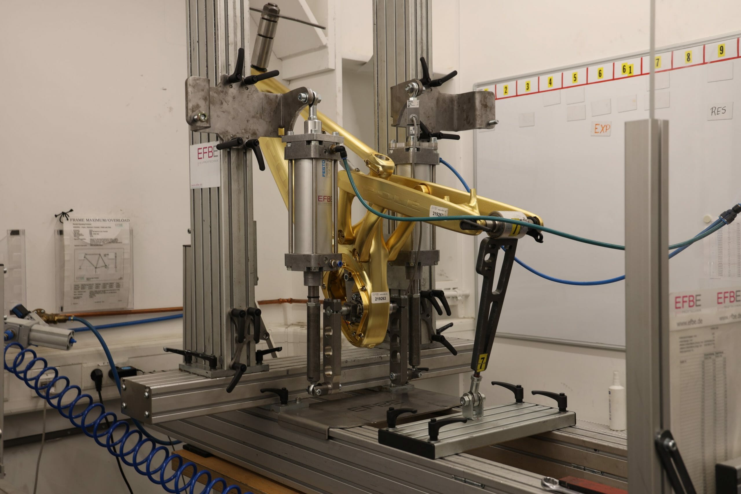
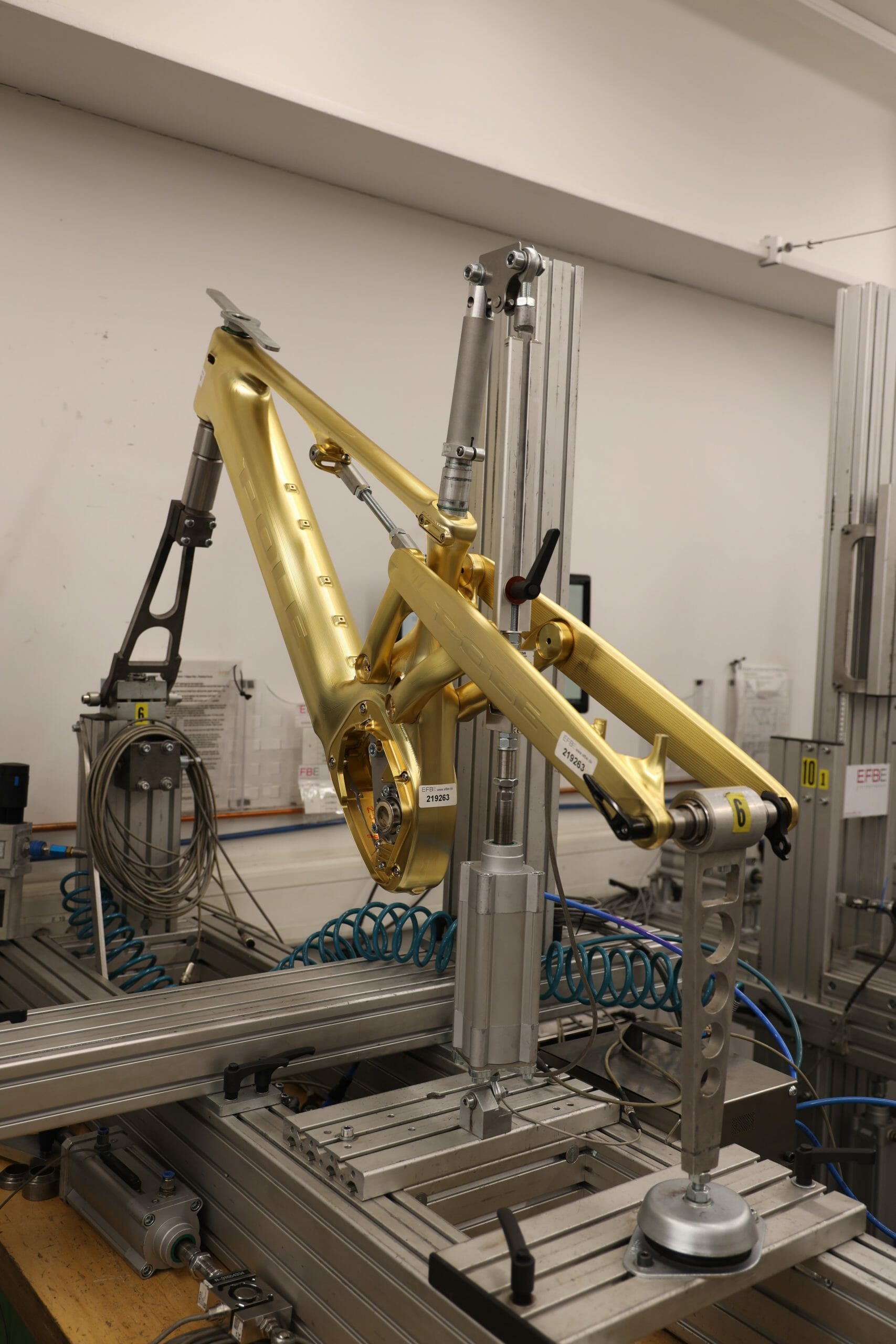
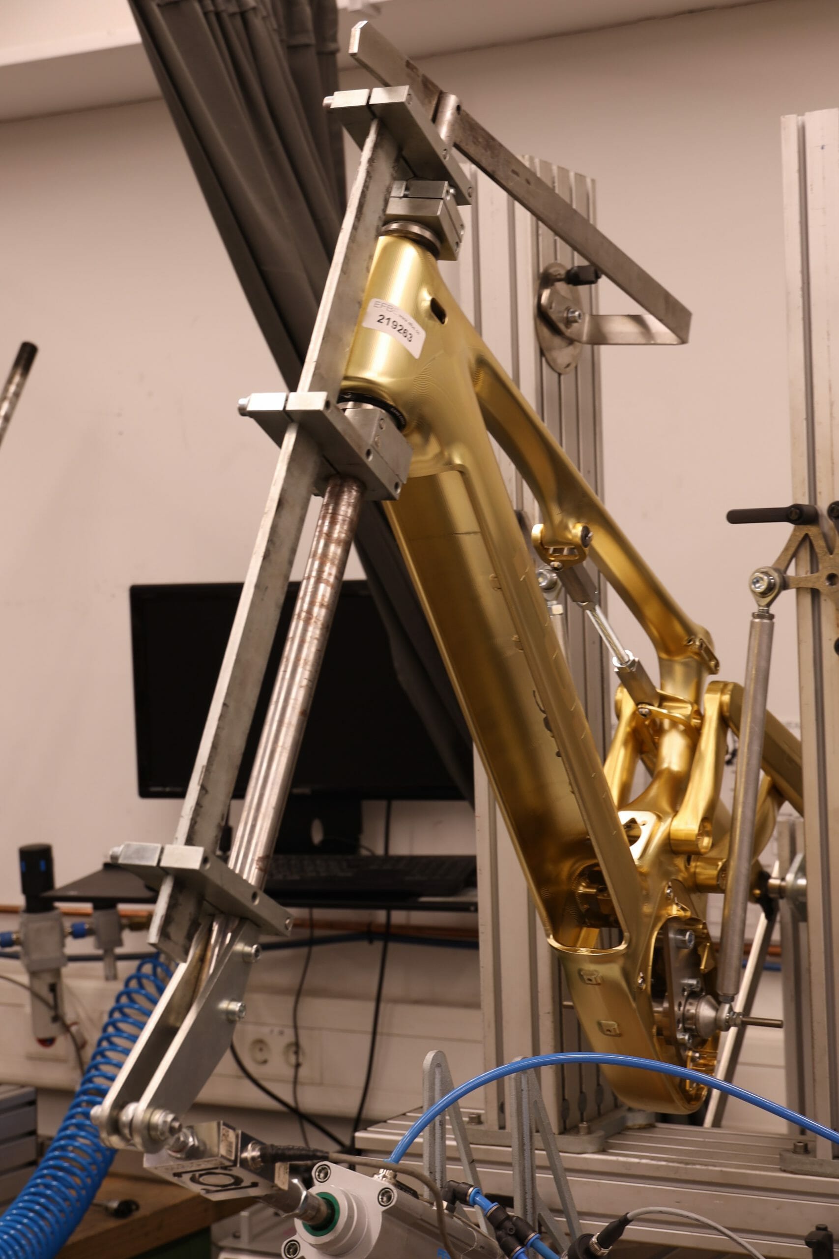
Let’s go through the test stages one by one to see what they entail. In all of the tests, the frame is mounted to the testing rig and the shock is replaced with a rigid member with the suspension set either to 30% (approximately around sag point) or 100% (full compression). A rigid dummy fork is used to connect the headtube to the testing rig to simulate the loads a suspension fork would encounter and transfer to the frame in real riding conditions.
A word of warning though! This section is somewhat technical. Feel free to skip it and jump straight to the conclusions if you wish…
Pedaling Forces Fatigue Test
The test simulates stresses caused by the pedaling forces. Dummy cranks are attached to the bottom bracket at a 45degree angle from a horizontal line. A force of 1300N is applied to the cranks for 100 000 cycles with a frequency of 10Hz or less. The test is similar to that of ISO 4210-6:2014, 4.3, but the forces are greater.
It’s worth pointing out that the pedaling forces simulated are much more than just light spinning. A world-class sprint track cyclist might be able to produce a pedaling force of 1300N, but numbers of this range aren’t achievable by most riders.
Vertical Force Fatigue Test
In this test, the frame is mounted from the axles to the rig while a vertical force of 1300N is applied to the seat post with an insertion depth of 120mm. The loading parameters are nearly identical to the first test: 1300N, 100 000 cycles, and 2-5Hz.
This loads the seat mast area of the frame heavily, and everything below it. A similar loading in real riding conditions would most likely require a year’s worth of laps on a bike park – seated.
Head Tube Fatigue Test
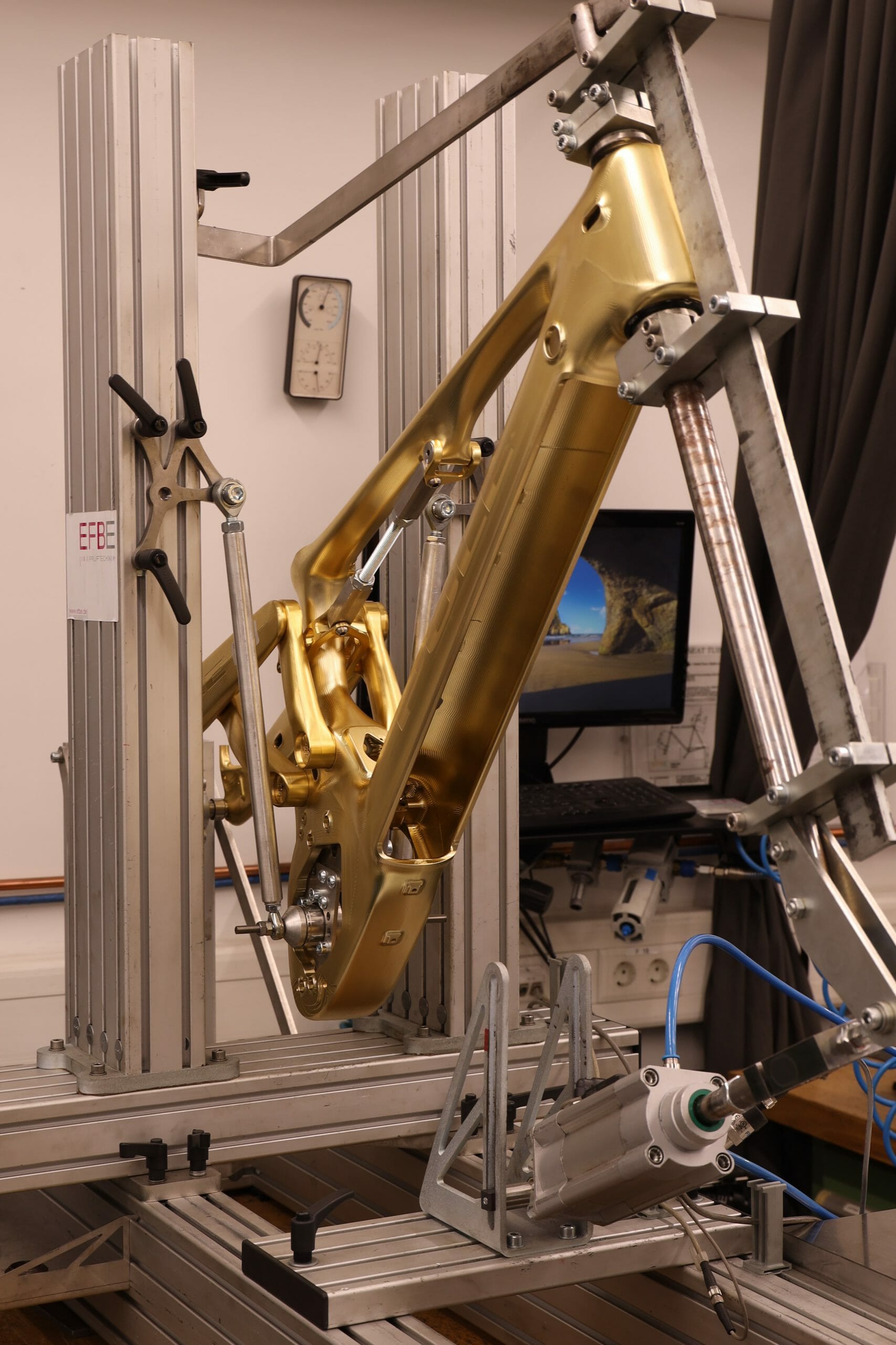
As the name implies, the test is used to check the strength and fatigue characteristics of the headtube area. A dummy fork is used to mount the headtube while an alternating + 600N/-1200 N test force is applied at the front wheel axle, perpendicular to the steering axis. The rear axle 100,000 load cycles are used once again with a frequency of less than 10Hz.
Brake Load Fatigue Test
This stage stimulates stresses caused by braking with a 203mm rotor. The frame is mounted to the rig from the rear axle and from the head tube with the aid of a dummy fork. An alternating horizontal force of +200N/-400N is applied to the disc brake rotor jig which in turn stresses the disc brake mount, simulating braking action.
Again, 100,000 load cycles were used with a frequency of 10Hz or less.
Rear Axle Load Fatigue Test
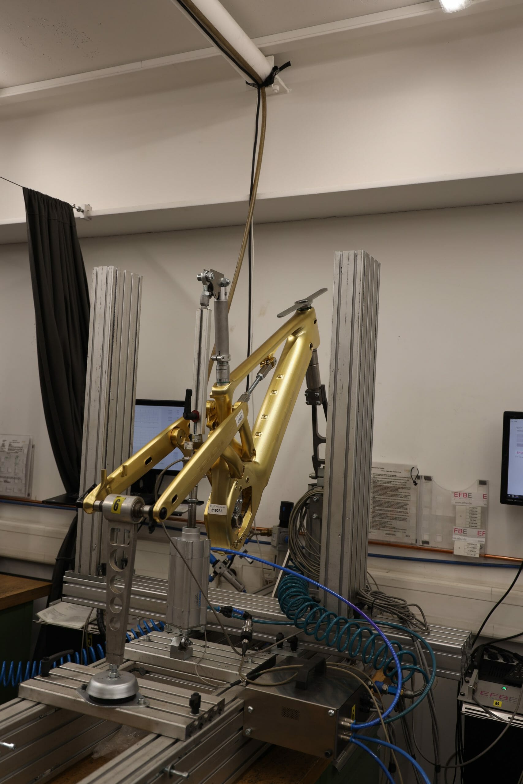
The frame is fixed to the rig from the bottom bracket and from the head tube with the aid of a dummy fork. A vertical force of 2100N is applied to the rear axle for 100,000 cycles with a frequency of 10Hz or less. As opposed to the previous tests, the rear suspension is set to 100%, to simulate a full bottom-out suspension scenario.
Lateral Load Fatigue Test
The lateral load test simulates a situation in which the frame is loaded heavily in a lateral direction (meaning sideways). A prime example of a corresponding real-world situation would a high-speed berm where a change of direction happens very fast – something that the Pole EWS team does day in, day out.
The frame is mounted to the rig from the bottom bracket and headtube similarly as in other test stages, while an alternating sideways load of +-400N is applied to the rear axle for 100 000 cycles at 100% suspension travel.
Maximum Load Test Pedal Load
The two most critical areas in frame design are the headtube and bottom bracket area. A sudden failure in either one of these areas can lead to dire consequences. This test verifies that the frame is up for the task when the bottom bracket is loaded heavily. A single-sided static load of 2500N at a lateral angle of 26degrees is applied to a dummy crank arm placed on the 6 o’clock position and then held for 10 seconds.
To pass this test, the frame must not show visible cracks, fractures, or permanent deformation at the point of application greater than 10mm.
Maximum / Overload Test Jump/ Drop Load
Finally, we have “the Big Case test”. The frame is once again supported by the dummy fork and a from the rear axle. The rear axle support fixture is placed 15degrees from the vertical to replicate a situation in which the wheelbase lengthens. A force of 6000N is applied vertically to the dummy crank arm mounted to the bottom bracket and held for 10 seconds.
The passing criteria are the same as in the previous tests, no cracks or deformation greater than 10mm should be observed. It does not end here though! After the test, the frame needs to withstand a force of 1000N applied in the same manner with no brittle fractures or other catastrophic failure modes.
It passed!
Passing the very demanding EFBE TRI-TEST® Gravity Cat-5 doesn’t happen by coincidence. It requires either an overbuilt frame or smart engineering. We rely on the latter. First, the test in question is developed to test downhill bikes which gives some strong hints of its highly demanding nature. Very few enduro frames have been tested this way and even fewer E-bike frames have completed the grueling eight stages of the test. This gives the Voima E-bike a pretty prestigious status.
Thanks to the use of superior 7075 T6 aircraft aluminum, our self-developed, and all-new CNC machining procedure, the Voima E-bike is one of the few frames belonging to this unique club.
Our aerospace-grade aluminum has nearly 1.5-fold tensile strength compared to the weldable 6000 and 7000-series alloys. Besides the base material and the design, the bonding is more than adequately strong to cope with the high demands of modern gravity riding – and passing the EFBE TRI-TEST® Gravity Cat-5 with flying colors is a testament to this.
The very fact that the frame has an enormous hole at the bottom of the downtube (which houses the PowerTube 750 battery) is proof that our bonding processes and frame design can withstand the punishment. It’s worth pointing out that the rear suspension swing arm is bridgeless too. Smart design with double-bearing linkages create a proven strong and stable platform for the Voima also.
As pioneers of New School Geometry, we don’t benchmark other brands; we create things our own way and believe only in the stopwatch – it doesn’t lie. Our in-house design and production, allow us to innovate fast. It sets us apart from others and is the reason why are the leading brand in New School Geometry.